FUNDAMENTAL CIRCUIT COMPONENTS
Let's look upon some of the basic components that are most commonly used while making circuits like Resistors, Capacitors, Inductors, Variable Resistors etc.
Active components are the elements or devices which are capable of providing or delivering energy to the circuit. Passive components are the ones that do not require any external source for the operation and are capable of storing energy in the form of voltage or current in the circuit.
Examples of the active components are diodes, transistors, integrated circuits, etc. similarly, examples of the passive components are resistor, capacitor, and inductor.
The active component does not require an external source for the operation, whereas the passive components require any external source for the operation.
A resistor is a passive electrical component with two terminals that are used for either limiting or regulating the flow of electric current in electrical circuits. The main purpose of resistor is to reduce the current flow and to lower the voltage in any particular portion of the circuit.
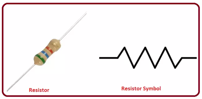
The electrical resistance of a resistor is measured in ohms. The symbol for an ohm is the greek capital-omega: Ω. The definition of 1Ω is the resistance between two points where 1 volt (1V) of applied potential energy will push 1 ampere (1A) of current.
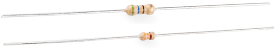
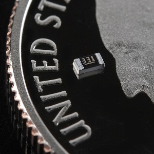
Resistors will come in one of two termination-types: through-hole or surface-mount. These types of resistors are usually abbreviated as either PTH (plated through-hole) or SMD/SMT (surface-mount technology or device).
Through-hole resistors come with long, pliable leads which can be stuck into a breadboard or hand-soldered into a prototyping board or printed circuit board (PCB).
Surface-mount resistors are usually tiny black rectangles, terminated on either side with even smaller, shiny, silver, conductive edges. These resistors are intended to sit on top of PCBs, where they're soldered onto mating landing pads.
You can read more about how to decode Through-hole resistor color codes and Surface mount markings here
When resistors are combined in series or parallel, they create a total resistance, which can be calculated using one of two equations. Knowing how resistor values combine comes in handy if you need to create a specific resistor value.
When connected in series resistor values simply add up.

The total resistance of N resistors in parallel is the inverse of the sum of all inverse resistances. This equation might make more sense than that last sentence:
 As a special case of this equation: if you have just two resistors in parallel, their total resistance can be calculated with this slightly-less-inverted equation:
