FUNDAMENTAL CIRCUIT COMPONENTS
Let's look upon some of the basic components that are most commonly used while making circuits like Resistors, Capacitors, Inductors, Variable Resistors etc.
Active components are the elements or devices which are capable of providing or delivering energy to the circuit. Passive components are the ones that do not require any external source for the operation and are capable of storing energy in the form of voltage or current in the circuit.
Examples of the active components are diodes, transistors, integrated circuits, etc. similarly, examples of the passive components are resistor, capacitor, and inductor.
The active component does not require an external source for the operation, whereas the passive components require any external source for the operation.
A resistor is a passive electrical component with two terminals that are used for either limiting or regulating the flow of electric current in electrical circuits. The main purpose of resistor is to reduce the current flow and to lower the voltage in any particular portion of the circuit.
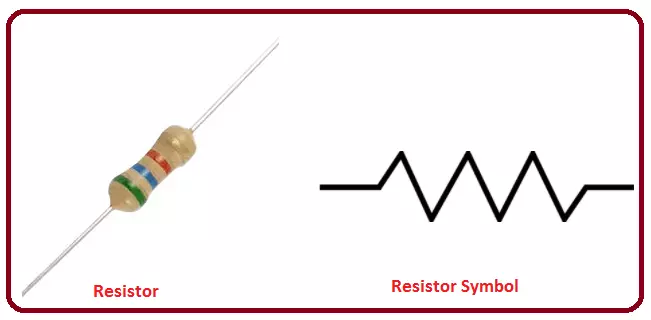
The electrical resistance of a resistor is measured in ohms. The symbol for an ohm is the greek capital-omega: Ω. The definition of 1Ω is the resistance between two points where 1 volt (1V) of applied potential energy will push 1 ampere (1A) of current.
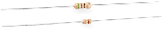
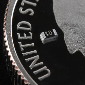
Resistors will come in one of two termination-types: through-hole or surface-mount. These types of resistors are usually abbreviated as either PTH (plated through-hole) or SMD/SMT (surface-mount technology or device).
Through-hole resistors come with long, pliable leads which can be stuck into a breadboard or hand-soldered into a prototyping board or printed circuit board (PCB).
Surface-mount resistors are usually tiny black rectangles, terminated on either side with even smaller, shiny, silver, conductive edges. These resistors are intended to sit on top of PCBs, where they're soldered onto mating landing pads.
You can read more about how to decode Through-hole resistor color codes and Surface mount markings here
When resistors are combined in series or parallel, they create a total resistance, which can be calculated using one of two equations. Knowing how resistor values combine comes in handy if you need to create a specific resistor value.
When connected in series resistor values simply add up.

The total resistance of N resistors in parallel is the inverse of the sum of all inverse resistances. This equation might make more sense than that last sentence:
 As a special case of this equation: if you have just two resistors in parallel, their total resistance can be calculated with this slightly-less-inverted equation:

A potentiometer is a manually controlled variable resistor with 3 terminals. Two of the terminals are connected to the opposite ends of a resistive element, and the third terminal connects to a sliding contact, called a wiper, moving over the resistive element. The potentiometer essentially functions as a variable resistance divider. The resistive element can be seen as two resistors in series (the total potentiometer resistance), where the wiper position determines the resistance ratio of the first resistor to the second resistor. If a reference voltage is applied across the end terminals, the position of the wiper determines the output voltage of the potentiometer.

For more clear understanding on how potetiometers work, I recommend watching this video.
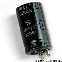
A capacitor is a little like a battery but works completely differently. A battery is an electronic device that converts chemical energy into electrical energy, whereas a capacitor is an electronic component that stores electrostatic energy in an electric field. It consists of two electrical conductors that are separated by a distance. The space between the conductors may be filled by vacuum or with an insulating material known as a dielectric. The ability of the capacitor to store charges is known as capacitance.
Watch this video to clearly understand the internal working of a capacitor and how it stores charge and discharges, and it's various uses.
The various types of capacitors that are used in electrical circuits are shown below:

Just like resistors, we can have series and parallel combinations for capacitors too, but capacitors behave differently than resistors :

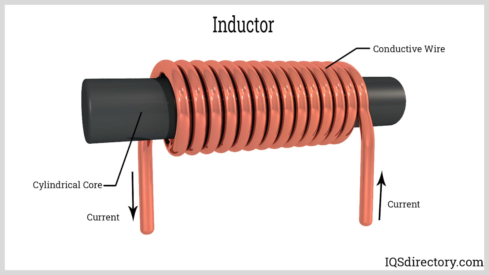
Inductors are coil-like structures that are found in electronic circuits. The coil is an insulated wire that is looped around the central core. Inductors are mostly used to decrease or control the electric spikes by storing energy temporarily in an electromagnetic field, and then releasing it back into the circuit. Whenever the current across the inductor changes, it either acquires charge or loses the charge in order to equalise the current passing through it. The inductor is also called a choke, a reactor or just a coil. An inductor is described by its distinctive nature of inductance, which is defined as the ratio of the voltage to the rate of change of current. Inductance is a result of the induced magnetic field on the coil.
We've seen that both capacitors and inductors store charge . So what is practically the difference between the two?.
| Feature | Capacitor | Inductor |
|---|---|---|
| Energy Storage | Stores energy in an electric field between two plates | Stores energy in a magnetic field around a coil |
| Opposition to Change | Opposes changes in voltage | Opposes changes in current |
| Behavior with AC Signals | Acts as a low impedance path for high-frequency signals | Acts as a high impedance path for high-frequency signals |
| Phase Relationship | Voltage leads current by 90 degrees | Current leads voltage by 90 degrees |
Neither is universally "better"; the choice depends on the application.
- High-frequency AC filtering or decoupling.
- Storing small amounts of energy.
- Designing compact circuits.
- Blocking DC while passing AC.
- Low-frequency AC filtering (e.g., power lines).
- Energy transfer in transformers or SMPS.
- Situations requiring high current handling.
- Smoothing current in DC-DC converters.
So far we've looked at a couple of passive components that are used in circuits, but to power up these components, we need some active components like batteries. Let's look into more details about batteries and power sources.